
Electrical resistance causes confusion because ‘resistance’ is only a metaphor
The idea of electrical resistance is a horrible concept, and causes no end of confusion, though people are rarely aware that they’ve been confused. It’s one of the main reasons why the rope loop is such a problematic model for electric circuits.
Electrical resistance has to tell two stories - one about flow and one about energy. It’s good at telling a flow story - big resistance means less flow - but it’s bad at telling an energy story.
This is because when we encounter ‘resistance’ in everyday situations - for example pushing through a jostling crowd or walking through mud, or some kind of friction - we tend to respond to it in one of two ways. Either we work harder to keep our movement the same, or we move slower until our rate of working is the same.
This is the exact opposite of how batteries behave - when we increase the resistance in a circuit the battery provides a smaller current, works less hard and causes less heating.
This assumption that electrical resistance shares all the properties of mechanical resistance leads teachers to aim for the wrong things when they create analogies and visualisations.
At a macroscopic scale, they may assume that the current has to struggle to make its way through a big resistance, causing more heating, and that the battery has to work harder to ‘overcome’ the resistance.
At a sub-microscopic scale, they may assume that resistances must slow charges down locally - whereas in fact they move faster in the narrow filament of a bulb or the electron-poor material of a carbon resistor.
Electrical resistance is a legacy concept that we’re stuck with for historical reasons
The idea of electrical resistance comes from the observation that if you have two different components with the same p.d. across them then the current will be smaller in one and bigger in the other.
By the 1820s current (measured by its magnetic effects - hence electrical ‘intensity’, I) was thought of as probably a flow or movement of some kind of fluid. Atoms had only been widely accepted within the previous twenty years, and the idea that atoms might themselves be made of even smaller parts wasn’t discussed seriously for another thirty.
But, regardless of what electric stuff might be in motion, it made sense that a smaller current meant a slower flow. If the current was smaller then a reasonable explanation was that there was something slowing it down.
We tend to experience things slowing down when they encounter what we might call a resistance - cars slow down as they go through mud or over a bumpy track; a pebble slows down if you drop it into water.
Presumably then the smaller current was due to something about the material through which the current was flowing ‘resisting’ its flow.
And it’s this image that we’ve ended up with today as the definition of resistance - something like ‘opposition to the flow of electric current’. I would argue that this definition of resistance is a mechanical metaphor for systems that are not mechanical by nature.
By non-mechanical I don’t mean we need to get into the weeds of quantum theory (which I don’t understand) or even advanced classical electrodynamics (which I also don’t understand), but that there is no natural classical mechanical system that explains electric circuits in a simpler and more intuitive way than simply understanding the physics of electric circuits in the first place.
Resistance has to explain two perspectives: visible and sub-microscopic across two dimensions: energy and current
This is a lot to ask of a mechanical analogy, and unsurprisingly no analogy that I know of can do this in a way that accounts for the facts in all four quadrants of the matrix below.
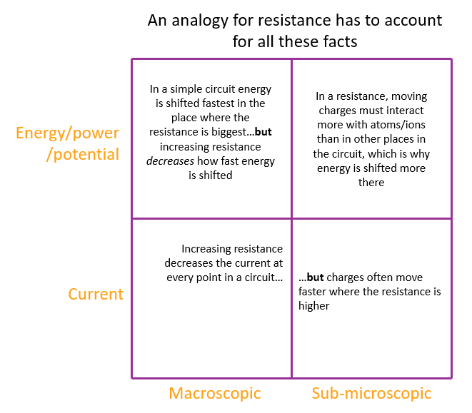
Let’s have a look at each of the quadrants to understand the challenges of finding an appropriate mechanical analogue.
In a simple circuit energy is shifted fastest in the place where the resistance is biggest, BUT increasing resistance decreases how fast energy is shifted.
So there are two separate questions:
Where is energy shifted?
What is the effect of increasing resistance?
In the circuit simulation below you can see that energy is shifted at the bulb (i.e. the only place in this circuit where there is any resistance), and that if you increase the resistance of the bulb (by swapping the bulb each time with a higher resistance one) the power of the bulb decreases (i.e. energy is shifted slower).
At a high level, increasing the resistance decreases the current while the p.d. stays the same, and since P=IV, the power must decrease.
But why does energy get shifted where the resistance is? One approach is to say it’s a useful rule of thumb - that’s the one I’d go for in class.
The other is to say that it’s a truism - a tautology. By definition a high resistance needs a big p.d. for a given current, and by definition a big p.d. occurs where energy is shifted quickest for a given current.
In our simple idealised circuit simulation, the only non-zero potential difference is across the bulb, since we model the rest of the circuit as having zero resistance.
So simply by the way we’ve defined our terms it must be the case that energy is shifted quickest where the resistance is.
One reason why this is so hard to model in a mechanical system is because of the underlying assumption that is almost never mentioned - that power supplies are designed to keep their voltage constant, and respond to changes in load resistance by changing the current they deliver only. Modelling a supply voltage mechanically with this behaviour is very hard - the rope loop analogy fails at this hurdle.
You can have a go with a gravitational analogue for potential, for example by dropping marbles through liquids of various viscosities or using a water loop with a fixed head, but these tend to fall over in one of the other quadrants and/or are just as complicated to understand as the circuit itself.
For me, I would just teach these two rules of thumb for simple circuits, and bring them to life with the circuit simulation
Heating happens where the resistance is
BUT increasing resistance decreases heating, because the current decreases
Increasing resistance decreases the current at every point in a circuit, BUT charges often move faster where the resistance is higher
The simplest rule about resistance is: Big resistance means small current.
Rather than use a mechanical analogy (like a marble dropped through syrup moves slower than a marble dropped through water) to explain why big resistance means small current, I would use it as a way to remember the rule.
At the same time I think you have to introduce the idea that batteries are lazy, and respond to big resistances, not by working harder to ‘overcome’ the resistance like we might do when we walk over soft sand, but by working less hard.
Batteries respond to a higher resistance by working less hard, and they work less hard by supplying a smaller current. I would say that this is why you have to be really careful with the idea of electrical ‘resistance’. Batteries are not constant current providers, and there isn’t a specific current they’re trying to supply that gets ‘resisted’.
The fact that increasing resistance decreases current everywhere in a simple circuit, but that charges often go faster through the actual resistance seems to be a bit of a paradox. This time, though, there are several mechanical analogies to show why it’s true. Even though these analogies exist, they tend not to be used very well, and the most common explanations involve charges moving slower through the resistance, rather than causing a slowing down everywhere else.
In general, mechanical analogies are better at explaining the effects of resistance on current than they are at explaining the effects of resistance on the rate at which energy is shifted (i.e. power).
Mechanical analogies for ‘resistance’ decreasing current everywhere, but with the speed locally high where the ‘resistance’ is:
A queue of people going through a turnstile - the people move quickest at the actual turnstile
Getting on a rollercoaster from a long queue - where people step from the platform into the cars is where the people move quickest
A river going through a narrow gorge - the water has to flow quicker where the river is narrower (though the effect on the overall flow of this constriction is less obvious)
All these examples illustrate how you can have the same ‘current’ (the number of people/ volume of water that pass a point anywhere in the system in a given time is the same), even though the speeds they move at are different.
The animation below shows 12 black dots passing a point in the same time, but the different widths mean they move at different speeds - the narrower the ‘wire’ the bigger the speed.
Remember this is meant to show how charges in a series circuit can move at different speeds if the wires have different thicknesses, even though the current (the number of coulombs of charge passing a point each second) is still the same. However if you change the thickness of any of the wires then you change the current everywhere, and so you have to include that when you work out what will happen to the speed of the charges.
In a resistance, moving charges must interact more with the atoms/ions than in other places in the circuit, which is why energy is shifted more there
As I’ve argued above, mechanical analogues for resistance tend to concentrate only on the reduction in current (mostly) or only on energy (rarely, and mostly incorrectly, because they argue that big resistance cause energy to be shifted quicker, rather than slower, as is the case).
I’ve also said that in a simple circuit energy is shifted quickest where resistance is highest simply by the way we’ve defined resistance. But this is a bit a of cop out, and we need to account for why certain parts of the circuit shift energy quicker than others, without resorting to the concept of resistance itself.
For this, we tend to use a sub-microscopic perspective. It’s much more complicated than what I’m about to describe, but the model below is good enough for our needs.
Imagine an isolated piece of metal wire. All the particles are moving randomly and super-fast. This movement is what we mean by thermal energy. The free electrons whizz around at about 1% of the speed of light and crash into the rapidly vibrating ionic lattice - typically each electron experiences about a trillion interactions per second. The wire and the surroundings are all at the same temperature, so there’s no net transfer of energy between the electrons and the ions, and the wire and the surroundings.
Because the energy transfers all net out to zero, we can just ignore the thermal interactions at a macro scale when we think about current. We can treat the electrons as if they were stopped when no current is flowing.
When a current flows, the electrons move through the lattice and interact with the ions.
In the thick wires, the electrons move slowly - a fraction of a millimetre per second - and have of the order of a few hundred interactions per second.
In the extremely thin filament of the bulb the electrons have to move much faster to keep the current the same everywhere - of the order of half a metre per second. Each electron may have a hundred thousand interactions per second.
This is much, much smaller than the number of interactions due to the thermal speed of the electron. But this small number of extra interactions make a huge difference because they are not in thermal equilibrium with the lattice - the electrons cause the lattice to vibrate more than the lattice gives back to the electron.
The dynamic equilibrium is now between the rate at which the power supply puts energy into the system and the wire takes energy out by heating the environment. The power supply adjusts the current it supplies (and thus how many electron-ion interactions there are each second) until the power in per ampere for the supply matches the power out per ampere for the wire - there is only one value of current where this can happen.
Zooming in to the electron level, there is an energy transfer rate from electrons to lattice that depends on:
the number of interactions each electron has with the lattice per second (and hence the current)
the composition and vibration of the ionic lattice, which in some complex way determines how easily the lattice allows electrons to transfer energy to it without giving it all back (which is why different metals have different resistances (strictly resistivities)).
The energy of the interactions doesn’t depend on the drift speed of the electrons along the wire, because this is typically only about a hundred thousandth of the random thermal speed. It’s the increase in the number of interactions per second due to the increase in local electron drift speed that’s important, not the increase in the energy of those interactions.
The mechanism whereby batteries keep their voltage constant but change the current and hence the power they provide so that this exactly matches the current, potential difference and power associated with the resistance is quite subtle, but gives a deep insight into circuits that’s worth engaging with.
You can use this idea of electron-ion interactions to explain why there’s more heating where the wire is thinner. The electrons have to move faster through the thin wire to keep the current the same everywhere, so there are more interactions per second with the lattice - the more interactions per second, the quicker energy is shifted from electrons to lattice.
Implications for teaching about resistance
So what should we teach if we want to get closer to a story that’s consistent with how circuits actually behave?
This is the story I’d tell if I was using a conventional approach - from the resistor’s perspective
When we connect different components to the same battery then an ammeter will show that some components cause a small current to flow and some a bigger current.
So some components slow the current down everywhere in the circuit more than others.
We say that this is a bit like the components having a resistance to the flow of current. The bigger the resistance, the smaller the current.
Components don’t really ‘resist’ the flow of current in a way that we’re familiar with, but it’s useful if we imagine that they do as a way to explain why the current is smaller.
In a simple circuit, the place where energy gets shifted is in the resistance. But if you increase the resistance the current gets smaller and so energy is shifted slower. So high resistance bulbs are dimmer than low resistance bulbs if you connect them to the same power supply.
This is the story I’d experiment with - from the battery’s perspective
When we connect different components to the same battery, a voltmeter will show that the battery voltage doesn’t change.
If we measure the current in the circuit, we can see that the current does change.
The battery responds to the presence of different components by changing the current it provides.
If the battery feels that the component provides a bigger resistance to the flow of current then the battery responds by providing a smaller current. The bigger the resistance the battery feels, the smaller the current it provides, and the less hard it works.
In a simple circuit, the place where energy gets shifted is in the resistance. But if you increase the resistance the current gets smaller and so energy is shifted slower. So high resistance bulbs are dimmer than low resistance bulbs if you connect them to the same power supply.